

Latest News
-

-

-

T113 External SPI NAND Storage Solution
2026-07-03 -

Ethernet Schematic Design for Allwinner T113
2026-07-03 -

Designing a Highly Interference-Resistant Isolated CAN Interface for Allwinner T153
1. Overview
In environments with strong electromagnetic interference — such as industrial control, smart grids, and automotive electronics — the CAN bus is widely used due to its high reliability and differential transmission characteristics. However, interference sources in the field, such as surges, electrostatic discharge, and ground potential differences, often intrude into the main control system through the CAN interface, causing communication packet loss in mild cases and burning the main control chip in severe cases. The Allwinner T153 features two built-in CAN interfaces and offers outstanding cost-effectiveness, making it well suited for industrial control product applications. Based on the Allwinner T153 platform, this article provides a detailed introduction to designing an isolated CAN interface with extremely strong anti-interference capability from three dimensions: power isolation, signal isolation, and bus protection.
2. Overall Architecture Design
2.1 Three-Level Protection Architecture
This solution adopts a three-level protection architecture of "power isolation + signal isolation + bus protection," establishing a complete electrical isolation barrier between the main control MCU and the CAN bus.
- First level: An isolated DC-DC module provides electrical isolation on the power side, cutting off the ground loop of common-mode interference.
- Second level: A digital isolator provides electrical isolation for CAN signals, blocking interference conducted along signal lines.
- Third level: A multi-stage protection network consisting of TVS, ESD, common-mode choke, and resettable fuses on the CAN bus side suppresses differential-mode and common-mode interference.
2.2 Isolation Boundary Division
The entire circuit is divided into two independent ground planes — the main control side (GND domain) and the CAN side (CAN_GND domain) — with the digital isolator and isolated power supply as the boundary. The two grounds are connected only through a 1 nF/2 kV high-voltage capacitor, providing a high-frequency discharge path while maintaining low-frequency isolation. The main control side uses 3.3 V and 5 V system power supplies, while the CAN side is powered independently by the isolated VDD_CAN. The two grounds are completely non-shared, fundamentally eliminating common-mode interference caused by ground potential differences.
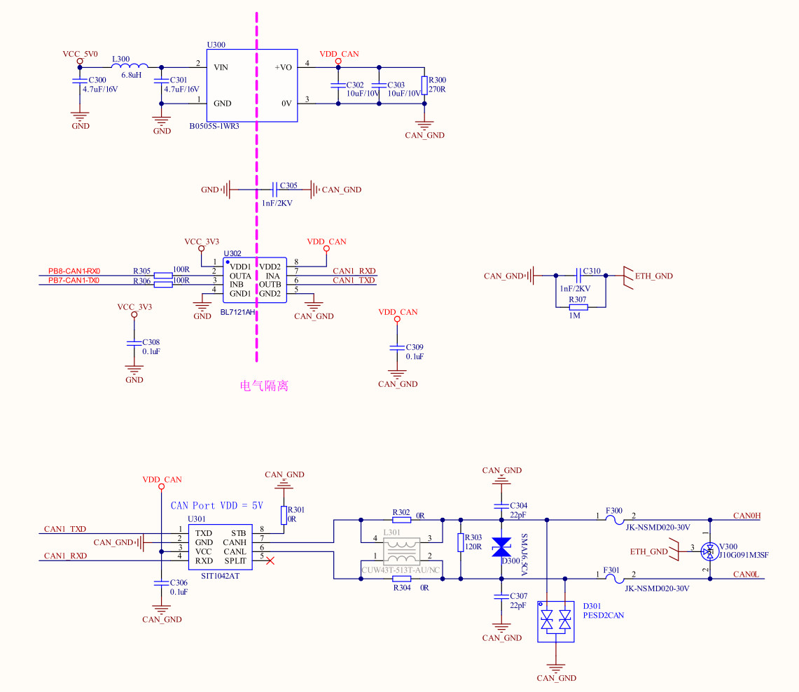
Figure 1: CAN Circuit
3. Power Isolation Design
3.1 Isolated DC-DC Selection
Power isolation uses the B0505S-1WR3 isolated DC-DC module, with 5 V input, 5 V output, and a rated power of 1 W. This module has an isolation withstand voltage of 3000 VAC and can effectively suppress ground potential differences and common-mode interference in industrial environments. A 6.8 µH inductor (L300) is connected in series at the module input, and together with 4.7 µF electrolytic capacitors C300 and C301, forms a π-type filter network to suppress ripple and noise on the input side.
3.2 Output Filtering and Dummy Load
- Two 10 nF ceramic capacitors (C302, C303) are connected in parallel at the output to filter out high-frequency noise.
- A 270 Ω dummy load resistor (R300) is connected in parallel at the output to ensure stable operation under light-load conditions and prevent output voltage drift.
- A 1 nF/2 kV high-voltage capacitor (C305) is connected across the isolated grounds to provide a discharge path for high-frequency common-mode interference without compromising low-frequency isolation.
4. Signal Isolation Design
4.1 Digital Isolator Selection
CAN signal isolation uses the BL7121AH dual-channel digital isolator, supporting a maximum transmission rate of 150 Mbps, fully meeting the CAN bus's maximum 1 Mbps communication requirement. This device provides two independent signal channels for bidirectional isolation of CAN_TX and CAN_RX signals, with an isolation withstand voltage of up to 2500 Vrms.
4.2 Signal Integrity Handling
- A 100 Ω resistor (R305, R306) is connected in series on each of the main-control-side PB7-CAN-TX0 and PB8-CAN-RX0 signal lines for impedance matching and current-limiting protection.
- A 0.1 µF decoupling capacitor (C308, C309) is placed close to each power pin on both sides of the isolator to ensure power supply stability.
- Independent ground planes (GND and CAN_GND) are used on both sides of the isolator to ensure the isolation effect is not compromised.
5. CAN Transceiver and Bus Protection
5.1 CAN Transceiver Selection
The CAN transceiver selected is the SIT1042AT, a high-speed CAN transceiver compatible with the ISO 11898 standard, supporting a maximum transmission rate of 5 Mbps. This chip offers excellent electromagnetic compatibility (EMC) performance, maintaining stable communication quality even in strong-interference environments. The STB pin is grounded through a 0 Ω resistor to place the chip in normal operating mode; the SPLIT pin is left unconnected.
5.2 Multi-Stage Bus Protection
- Resettable fuses: A JK-NSMD020-30V (0.2 A/30 V) resettable fuse (F300, F301) is connected in series on each of the CANH and CANL lines, automatically limiting current in the event of a bus short circuit and self-recovering after the fault is cleared.
- TVS protection: An SM712 (V300) TVS array provides surge protection between CANH/CANL and ground, withstanding electrostatic discharge and surge impacts of ±12 kV.
- ESD protection: A PESD2CAN (D301) dedicated CAN bus ESD protection diode provides low-capacitance, high-clamping electrostatic protection.
- Differential-mode TVS: An SMAJ6.5CA (D300) is connected in parallel between CANH and CANL to suppress differential-mode surge voltages.
5.3 Common-Mode Suppression and Filtering
- A common-mode choke L301 (CUW43T-313T-AU/NC) is connected in series in the CANH/CANL loop to effectively suppress common-mode interference with virtually no impact on differential-mode signals.
- CANH and CANL are each connected to CAN_GND through a 22 pF capacitor (C304, C307) to filter out high-frequency common-mode noise.
- A bus termination resistor R303 (120 Ω) is connected in parallel between CANH and CANL for bus impedance matching and to prevent signal reflection.
- CAN_GND and ETH_GND are connected through a 1 nF/2 kV capacitor (C310) and a 1 MΩ resistor (R307) to balance the potential between different interface grounds while maintaining isolation characteristics.
6. Weathink Industrial Communication Capabilities
Weathink has been deeply engaged in the industrial communication field for many years and has accumulated rich engineering experience in the anti-interference design of industrial interfaces such as isolated CAN, RS485, and Ethernet. From power isolation topologies to bus protection networks, from EMC debugging to reliability verification, Weixinke can provide customers with full-process technical support from solution design to mass production, helping products easily handle various complex industrial field environments.