
Latest News


Schematic Design for Connecting Allwinner T153 with External Audio CODEC ES8388
1. Overview
In the development of embedded industrial control and intelligent hardware, audio input and output are common functional requirements. As a high-performance, cost-effective industrial-grade processor, the Allwinner T153 does not feature a built-in high-performance stereo CODEC. To achieve high-quality audio playback and recording functions, an external dedicated audio codec chip becomes an inevitable choice. Based on the low-power stereo audio CODEC chip ES8388 from Everest Semi, this technical article will delve into the hardware schematic design, interface signal connections, and key peripheral circuit design points for its integration with the Allwinner T153 processor.
2. ES8388 Chip Features and Architecture Brief
The ES8388 is a high-performance, low-power, and low-cost audio codec chip. It integrates multi-bit Delta-Sigma modulators internally, features very low sensitivity to clock jitter, and exhibits extremely low out-of-band noise. Its core features include:
● ADC/DAC Architecture: Supports 24-bit sampling frequencies from 8 kHz to 96 kHz. The ADC dynamic range reaches 95 dB with a THD+N of -85 dB; the DAC dynamic range reaches 96 dB with a THD+N of -83 dB.
● Audio Interface: Supports standard digital audio serial interfaces such as I²S (Inter-IC Sound), Left Justified, and DSP/PCM, and supports both Master and Slave modes.
● Analog Functions: Integrates a microphone amplifier (Mic Amp), a 40mW headphone amplifier (Headphone Amp), Automatic Level Control (ALC), a noise gate, as well as flexible analog mixing and gain adjustments.
● Power Supply: Supports a wide operating voltage from 1.8V to 3.3V, featuring 7 mW low-power playback and 16 mW simultaneous playback and recording operation.
3. Digital Interface Circuit Design between T153 and ES8388
The communication between Allwinner T153 and ES8388 consists of two parts: the control bus and the digital audio data bus. In the schematic design, this is primarily divided into the following two key interfaces:
3.1 I²C Control Bus Connection
The ES8388 supports both I²C and SPI microcontroller configuration interfaces. In the Allwinner T153 solution, a standard 2-wire I²C bus is typically used for register configuration. During design, the SCL (serial clock line) and SDA (serial data line) of the ES8388 should be connected to the corresponding I²C controller pins of the T153. Additionally, 4.7kΩ pull-up resistors to 3.3V should be reserved on the signal lines to ensure the stability of bus communication.
3.2 I²S Serial Audio Digital Interface Connection
The transmission of digital audio signals is achieved via the I²S serial bus. In this system, the Allwinner T153 is typically configured as the Master device, and the ES8388 as the Slave device. The main pin connections are as follows:
● MCLK (Master Clock): The system master clock input, usually provided by the T153 at a frequency of 256Fs or 384Fs (such as I2S_MCLK or the general-purpose clock output CLK_OUT).
● BCLK (Bit Clock): The audio serial bit clock, generated by the master device T153.
● LRCK (Frame Clock / WS): The left/right channel frame clock, indicating whether the currently transmitted data belongs to the left or right channel.
● DACDAT: Digital audio playback data input, connected to the I2S_DO (Data Output) of the T153.
● ADCDAT: Digital audio recording data output, connected to the I2S_DI (Data Input) of the T153.
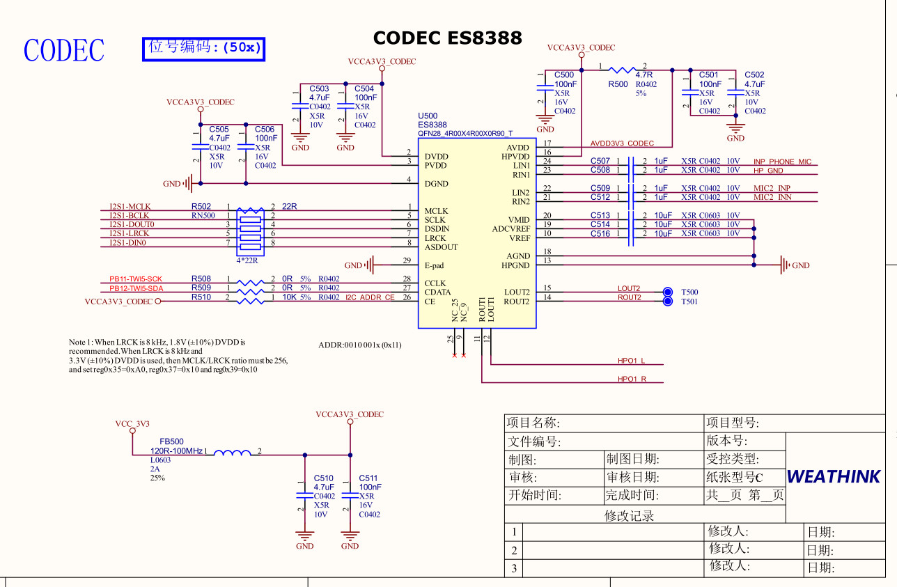
Figure 1: Schematic Diagram of T153 Connected to ES8388
4. Analog Input and Output Peripheral Circuit Design
4.1 3.5mm Headphone Output and Audio Power Amplifier Circuit
The ES8388 integrates a 40mW headphone amplifier, supporting both Capless (capacitor-less) mode and traditional AC-coupled mode. In the specific schematic design:
● Headphone Channels: The audio output pins LOUT1 and ROUT1 are connected to a 3.5mm stereo audio jack through series DC-blocking capacitors (typically 100µF to 220µF tantalum capacitors or low-ESR electrolytic capacitors used to filter out DC bias).
● Anti-Pop Design: Transient Voltage Suppression (TVS) devices for electrostatic protection should be connected in parallel at the headphone jack pins, and discharge resistors should be reserved on the signal lines to eliminate potential "Pop" noises (impact sounds) generated at the moment of plugging or unplugging headphones.
4.2 Microphone Input Bias Circuit
The ES8388 provides a built-in microphone bias voltage pin, MICB. In the input circuit design, an electret condenser microphone (MIC) requires a controlled DC bias voltage to function properly. The MICB pin should be connected to the positive terminal of the microphone through a 2.2kΩ bias resistor. Meanwhile, the audio signal is AC-coupled to the analog input pins of the ES8388 (such as LIN1 / RIN1) via a 1µF ceramic capacitor.
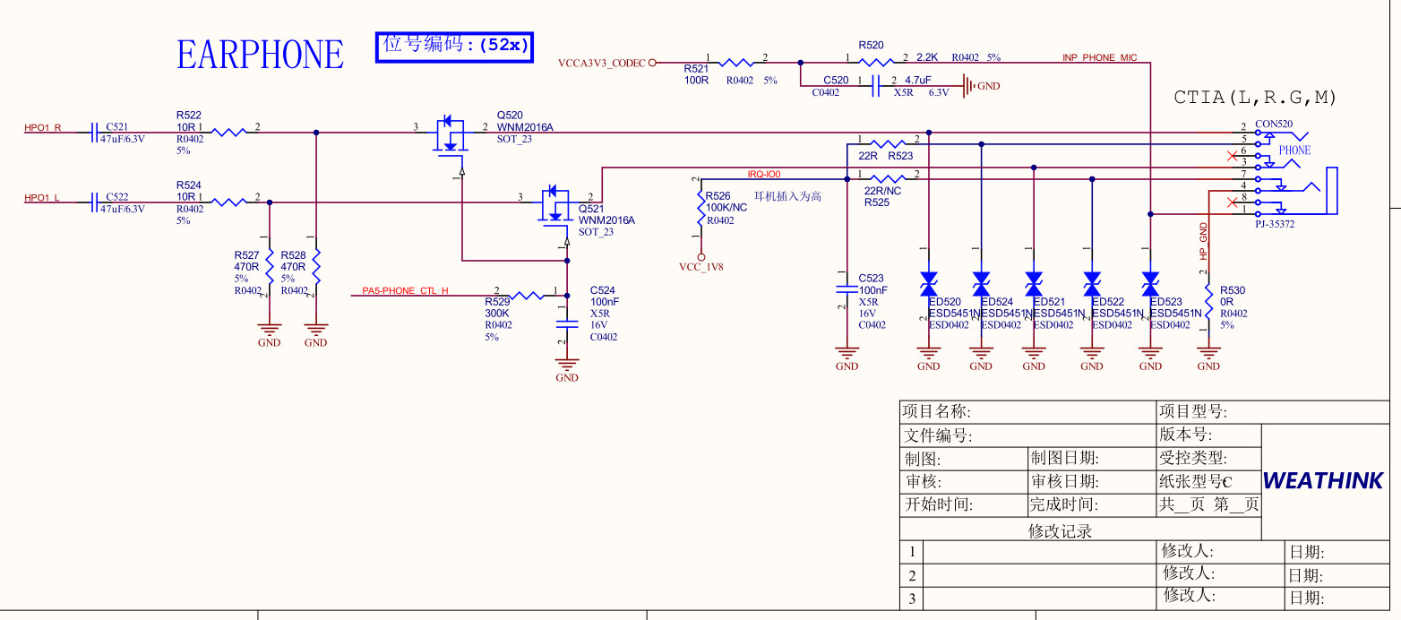
Figure 2: 3.5mm Headphone Interface Section
5. Power Management and PCB Layout Considerations
Audio systems are extremely sensitive to power supply noise. Since the ES8388 contains both digital and analog circuits internally, the following principles must be strictly followed in power supply design and layout:
● Separation of Digital and Analog Power: The analog power supply (VNDA/VCCA) and digital power supply (VDDD/VDDIO) should be isolated at the source using magnetic beads (high isolation) or discrete LDOs to prevent high-frequency digital noise from crosstalking into the analog audio channels.
● Decoupling Capacitor Configuration: Each power pin (such as VCCA, VCCD) must have a 0.1µF and a 10µF decoupling capacitor placed immediately adjacent to it, and the traces must pass through the capacitors before entering the pins.
● Reference Voltage Source Decoupling: The VREF loop is the reference source for the internal ADC/DAC of the CODEC. A low-ESR 10µF capacitor and a 0.1µF capacitor must be connected directly to the analog ground, and this trace should be kept as short as possible.
6. Message from Weathink, an Ecosystem Partner
● As an official ecosystem partner of Allwinner, Weathink has long been dedicated to providing highly cost-effective hardware solutions for industrial control, intelligent hardware, and edge computing fields.
● Leveraging professional hardware customization services and deep expertise in signal integrity technology, Weathink provides customers with efficient, stable Allwinner core boards and customized carrier board designs, helping projects accelerate their time-to-market.