
Latest News
-

HDMI RX Schematic Design of Rockchip RK3588
2025-09-08 -

-

-

-

HDMI RX Schematic Design of Rockchip RK3588
The Rockchip RK3588 is a high-performance SoC chip widely used in edge computing, AI applications, industrial control, multimedia terminals, and other fields. The chip integrates a rich set of video interfaces, including HDMI 2.1 TX and HDMI 2.0 RX. In certain scenarios, especially those involving video capture and signal input, the design of the HDMI RX (receiver) interface is particularly critical. The RK3588 supports HDMI 2.0 RX and is backward compatible with HDMI 1.4b. It supports RGB/YUV444/YUV422/YUV420 formats and can handle input up to 4K@60Hz.
This article explains the schematic design methodology for HDMI RX based on RK3588, covering system architecture, interface definitions, circuit design, signal integrity, and ESD protection.
1. Overview of HDMI RX
HDMI RX (High-Definition Multimedia Interface Receiver) is used to receive video and audio signals output from external devices such as set-top boxes, cameras, gaming consoles, etc. RK3588 supports HDMI 2.0 RX functionality, with a maximum supported resolution of 4K@60Hz, offering strong multimedia processing capabilities.
2. System Architecture Overview
The HDMI RX module inside RK3588 includes the following core components:
TMDS Decoder: Receives high-frequency differential signals and decodes them into digital data streams.
HDCP Decryption Module: Supports HDCP 1.4/2.2 protocols to ensure secure content transmission.
CEC Controller: Supports inter-device control between HDMI devices.
EDID Manager: Exchanges display capability information with the source device.
RK3588 connects to external HDMI receiver interface chips or ESD protection components through dedicated HDMI_RX signal pins.
3. Key Points of Schematic Design
3.1 HDMI RX Interface Definition
The HDMI RX interface of RK3588 typically includes the following signals:
Signal Name Direction Description
RX2+/RX2- Input TMDS Channel 2 Differential Input
RX1+/RX1- Input TMDS Channel 1 Differential Input
RX0+/RX0- Input TMDS Channel 0 Differential Input
RXC+/RXC- Input TMDS Clock Differential Input
HPD Input Hot Plug Detect, high level indicates connection
DDC_SCL/DDC_SDA Bi-dir I2C communication for EDID reading
CEC Bi-dir Consumer Electronics Control signal
+5V Input HDMI interface power detection
3.2 Differential Signal Design
Impedance Control: TMDS signals require 100Ω differential impedance, and strict routing control is necessary.
Length Matching: Differential pairs across all channels must be matched within ±25mil.
Equal Length, Equal Spacing, Coplanar Routing: To avoid signal reflection, crosstalk, etc.
3.3 ESD Protection Circuit
As the HDMI interface is exposed to users, ESD protection components are essential. Components like ESD5304D can be used to protect TMDS and control signals.
3.4 Power Supply and Detection
The +5V from the HDMI interface is not used to power RK3588 directly, but rather for detection and EDID power.
Design should include current-limiting resistors and TVS diodes for protection.
After detecting the +5V voltage level, the HDMI RX module can be powered on or initialized accordingly.
3.5 I2C DDC Line Design
DDC lines are used for EDID data exchange between the display and source device.
RK3588 integrates an internal I2C controller and requires pull-up resistors (typically 4.7kΩ).
Voltage Compatibility: DDC is 5V-tolerant, while RK3588 operates at a 3.3V core. Level shifters or integrated solutions are recommended.
4. Schematic Design
The following is based on the HDMI RX connection method of the WTC-RK3588-B SOM.
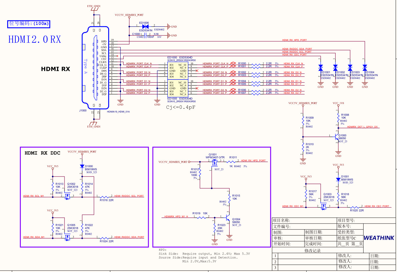
Figure 1. HDMI RX Connection for RK3588
4.1 ESD Protection
For HDMI RX TMDS signals, it is required to reserve a 2.2Ω resistor near the HDMI RX connector. This must not be omitted to enhance resistance against ESD surges.
4.2 Plug Detection Circuit
Since the HDMI RX controller does not support hardware detection of source plug/unplug events, detection must be handled in software. In hardware, the plug detection signal is implemented as HDMIRX_DET_L_GPIO1_D5.
4.3 Decoupling Capacitor
It is recommended to place a 0.1uF decoupling capacitor on Pin 18 of the HDMI connector, positioned close to the pin during layout. To improve ESD protection, ESD components must be reserved on the signal paths. For HDMI 2.0 signals, the ESD parasitic capacitance must not exceed 0.4pF; for other signals, it is recommended to use components with parasitic capacitance no greater than 1pF.
5. Circuit Design Considerations
ESD Protection: The HDMI port is highly susceptible to electrostatic discharge; ESD protection is essential.
Signal Integrity: High-speed differential signals must not have layer breaks, vias, sharp corners, or crossings.
Interface Compatibility: Ensure HDMI interface follows the HDMI 2.0 standard to avoid unknown compatibility issues.
Hot Plug Detection: The HPD signal can be connected to an interrupt trigger so that software can detect plug/unplug events.
6. Conclusion
With a proper circuit design, rigorous signal handling, and comprehensive protection schemes, the HDMI RX interface of RK3588 can stably and efficiently achieve high-definition video signal acquisition. For applications involving HD video input — such as video conferencing terminals, smart TV boxes, and industrial vision systems — RK3588 offers strong underlying support.
If a more straightforward method is preferred, you may consider using the WTB-RK3588-B industrial control board, which comes with an HDMI RX interface. During the design process, special attention should be paid to high-speed signal routing, voltage level compatibility, and HDCP authorization to ensure the entire system operates reliably and stably.