
Latest News


1. Overview
RK3588J is a high-performance AIoT processor developed by Rockchip, supporting multiple USB interfaces including USB 3.1 Gen1/Gen2. The USB Type-C interface is widely used in modern electronic devices due to its reversible plug orientation, high bandwidth, and multifunctional integration (e.g., PD, DP Alt Mode).
This document is based on Weathink's WTC-RK3588J-B SOM, and describes how to convert the RK3588J’s USB 3.0 interface into a USB Type-C interface, along with a typical schematic design.
2. USB 3.0 Interface on RK3588J
2.1 USB Interface Support on RK3588J
RK3588J supports multiple USB ports, including:
USB3.1 HOST × 2
USB2.0 HOST × 2
USB3.1 OTG × 1 (Supports Device/Host mode)
2.2 USB 3.0 Signal Description
USB 3.0 signals include:
TX+ / TX- (Transmit differential pair)
RX+ / RX- (Receive differential pair)
USB2.0 D+ / D-
VBUS, GND
ID (Used for Host/Device identification)
When designing a USB Type-C interface, it is crucial to consider USB 3.0 signals, USB 2.0 compatibility, and CC pin configuration.
3. USB Type-C Connector Basics
The USB Type-C connector includes the following pins:
VBUS / GND
USB2.0 D+ / D-
SuperSpeed TX/RX differential pairs: TX1+/TX1-, RX1+/RX1-, TX2+/TX2-, RX2+/RX2-
CC1 / CC2: Configuration channel pins used for role detection (Host/Device) and current level negotiation
SBU1 / SBU2: Used for audio/video channels
In a USB 3.0-only Type-C design, typically only one pair of TX/RX differential pairs is used, for example:
TX1+/TX1- ←→ RK3588J TX+
RX1+/RX1- ←→ RK3588J RX+
4. Typical Schematic Design
4.1 Schematic Overview
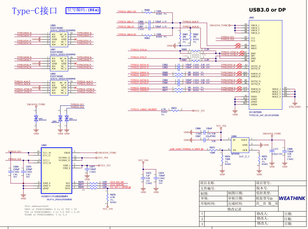
Figure 1: RK3588J USB 3.0 to Type-C Connection
4.2 USB 3.0 SuperSpeed Differential Pair Connection
RK3588J USB3.0 TX → Connect to Type-C TX1+/TX1- (or TX2+/TX2-)
RK3588J USB3.0 RX → Connect to Type-C RX1+/RX1-
Note: Ensure matched trace lengths and controlled impedance (90Ω differential).
4.3 USB 2.0 Connection
D+ / D- directly connect to Type-C A6/A7 (D+), A7/A6 (D-)
4.4 CC Pin Connection
Use a USB Type-C CC controller chip (this document uses FUSB302):
CC1/CC2 connect to the Type-C receptacle
The controller outputs Host/Device role status to RK3588J via I2C and INT pins
4.5 VBUS Control
VBUS is supplied by an external 5V power source, typically controlled through a current-limiting switch (e.g., TPS2561, MT9700)
Control signals can either come from RK3588J GPIOs or be automatically handled by the CC controller
5. Design Considerations
5.1 Differential Signal Routing
USB 3.0 differential pairs must be length-matched and impedance-controlled (90Ω differential)
Minimize vias and long stubs to avoid signal integrity issues
5.2 ESD Protection
Since the USB port is exposed externally, TVS diodes should be used for ESD protection
5.3 CC Pin Handling
Use a mature and reliable CC controller chip to simplify the design
For OTG support, ensure CC voltage detection and switching is implemented
5.4 VBUS Power Path
Add current protection and soft-start circuitry for stable VBUS output (e.g., TPS series chips)
6. Conclusion
When designing a USB 3.0 to Type-C interface based on RK3588J, it is essential to consider SuperSpeed differential pair routing, USB 2.0 compatibility, VBUS control, and CC pin recognition.
By carefully selecting the CC controller, power management IC, and ESD protection components, a stable and reliable USB Type-C interface can be achieved.
Choosing a reliable core board, such as Weathink's WTC-RK3588J-B, is also a key factor in ensuring success.
If you plan to expand support for PD (Power Delivery) or DP Alt Mode, additional design with PD controllers and advanced circuitry will be required.