
Latest News


TI AM6252 External ALC5616 Audio Codec Schematic Design and Key Points Analysis
Summary
This article provides a detailed introduction to the schematic design for connecting the TI AM6252 processor to an ALC5616 audio codec via the I2S interface. These design principles are also fully applicable to solutions based on the Weathink AM62x SOM, aiming to provide hardware engineers with a complete and practical design guide. The content of this article is crucial for developing audio-related products based on the TI AM6252 or AM625x series processors, serving as a valuable reference for understanding their hardware design.
If you encounter technical difficulties during development, or require more in-depth hardware design and software driver support, please feel free to contact us. The professional Weathink team will provide you with a one-stop solution.
1. AM6252 and Audio Codec: Why an External Solution?
The TI AM6252 is a high-performance, low-power application processor widely used in industrial HMI, gateways, and edge computing. Although it integrates multimedia functions, achieving high-quality audio input/output, supporting various audio formats, or special features (such as microphone arrays) typically requires connecting a dedicated audio codec chip.
In actual product development, to shorten the design cycle and reduce complexity, many engineers choose to use a SOM (System on Module, SOM). For example, by using the Weathink AM62x SOM, developers do not need to handle complex AM6252 core power and DDR routing, and can focus their energy on the schematic design of external peripherals such as the ALC5616 audio codec to achieve high-quality audio input/output.
An audio codec is responsible for converting digital audio data (e.g., from the AM6252) into an analog signal (playback) and converting an analog signal (e.g., from a microphone) into a digital signal (recording). The AM6252 communicates with the codec through standard interfaces, with the most common being I2S (Inter-IC Sound) and I2C (control).
2. Key Interfaces and ALC5616 Codec Selection
Before designing the schematic, it is necessary to select an appropriate audio codec chip. For example, the ALC5616 is a good choice with excellent compatibility with the AM6252. This codec chip typically integrates an ADC (analog-to-digital converter), DAC (digital-to-analog converter), and headphone/speaker drivers, offering comprehensive functionality.
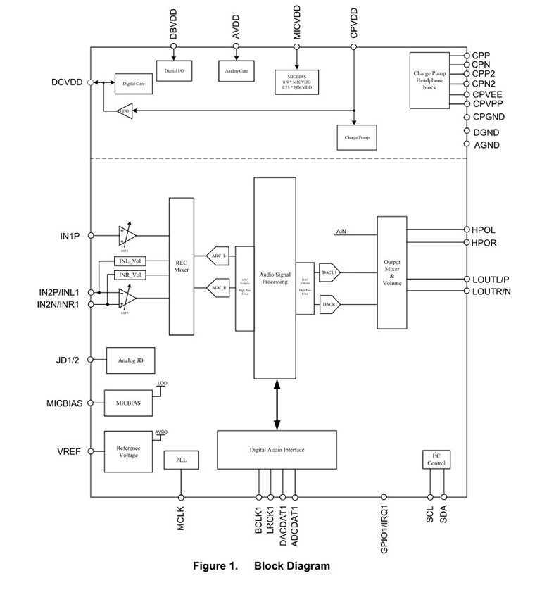
Figure 1 ALC5616 Block Diagram
2.1 I2S Interface: Audio Data Transfer
The I2S (Inter-IC Sound) interface is the core for transferring audio data between the AM6252 and the ALC5616. It typically consists of the following four signal lines:
BCLK (Bit Clock): The bit clock, used to synchronize the digital audio data stream.
WCLK (Word Clock) / LRCLK (Left-Right Clock): The word clock, used to identify the start of left and right channel data.
DOUT (Data Output): Digital audio data output, where the AM6252 sends audio data to the ALC5616.
DIN (Data Input): Digital audio data input, where the ALC5616 sends audio data to the AM6252.
Design Points:
Clock Source: The AM6252 can be configured as either I2S Master or I2S Slave.
Master Mode: The AM6252 provides the BCLK and WCLK, and the ALC5616 synchronizes as a slave device. This mode is relatively simple to configure and is the recommended first choice.
Slave Mode: The ALC5616 provides the BCLK and WCLK, and the AM6252 synchronizes as a slave device. It is necessary to ensure that the clock provided by the ALC5616 meets the timing requirements of the AM6252.
Pin Connections: In the schematic, connect the AM6252's I2S pins (usually found in the pin multiplexing table) directly to the corresponding I2S pins of the ALC5616. For example, the AM6252's MCLK (master clock) also typically needs to be connected to the ALC5616 to provide its reference clock. When using the Weathink AM62x SOM these I2S, MCLK, and other key interface signals are already routed out through the SOM's connectors, and developers only need to connect them according to the core board's pin definition.
2.2 I2C Interface: Codec Register Configuration
The I2C (Inter-Integrated Circuit) interface is used by the AM6252 to send control commands to the ALC5616, such as setting the sample rate, volume, gain, mode, etc.
Design Points:
SDA (Data) and SCL (Clock): Connect the AM6252's I2C pins to the ALC5616's I2C pins.
Pull-up Resistors: The I2C bus uses open-drain outputs, and pull-up resistors must be connected to the SDA and SCL lines. The resistor value is typically 2.2kΩ or 4.7kΩ, depending on the bus capacitance and operating frequency.
Address: The ALC5616 chip has a fixed I2C slave address that needs to be configured in the AM6252's software driver.
2.3 Reset and Interrupts
Reset (RESET): The ALC5616 chip typically has a reset pin. It is recommended to connect this pin to an AM6252 GPIO pin so that software can control the ALC5616's startup and reset timing.
Interrupt (INT): If the ALC5616 supports interrupt functionality (e.g., detecting headphone insertion/removal), its interrupt output pin can be connected to an AM6252 GPIO to generate an interrupt request for a quick response.
3. Power and Ground Design
Power is the foundation for stable operation, especially for audio codecs that mix analog and digital circuits.
Power Rails: The AM6252 typically uses 1.8V, 3.3V, and other power supplies. The ALC5616 chip also requires multiple power rails, such as the digital core power (DVDD), analog power (AVDD), and I/O power (IOVDD). Ensure that the IOVDD voltage of the ALC5616 matches the AM6252's I/O voltage to ensure level compatibility.
Decoupling Capacitors: Decoupling capacitors must be placed near each power pin of the ALC5616 chip, typically a combination of 0.1μF and 10μF, to filter out high-frequency noise and provide instantaneous current.
Grounding: This is a crucial point. To ensure audio quality, the analog ground (AGND) and digital ground (DGND) of the ALC5616 must be handled separately and then connected at a single point (e.g., near the ALC5616). For PCB layout, a complete ground plane should be used.
4. Schematic Example and Analysis
(Please upload your schematic here)
This schematic shows the actual connection details between the AM6252 processor and the ALC5616 audio codec. You can refer to this diagram to verify your design and focus on the following aspects:
Power Connections: Check that all power rails required by the ALC5616 (DVDD, AVDD, IOVDD) are correctly connected and have sufficient decoupling capacitors.
Signal Routing: Confirm that the I2S and I2C signal lines are connected directly and without interference.
Peripheral Circuits: Check that the filtering circuits, coupling capacitors, and headphone jack connections for the audio input/output sections are correct.
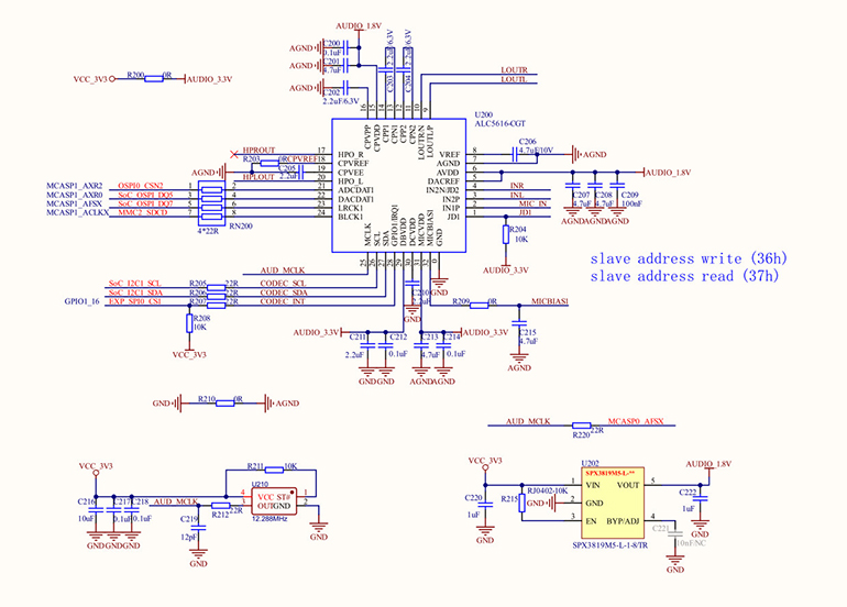
Figure 2: Connection of AM6252 to ALC5616
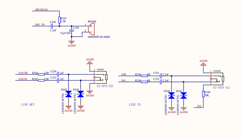
Figure 3: External interface of AM6252 connected to ALC5616
5. Key PCB Layout Considerations
A good PCB layout is key to ensuring audio quality and is even more important than the schematic itself.
Area Partitioning: On the PCB, separate the analog audio section (ALC5616's analog output, input, headphone interface) from the digital circuit section (AM6252, I2S, I2C) to prevent digital signal noise from interfering with the analog signals.
Ground Plane: Use separate analog and digital ground planes and connect them with a 0Ω resistor or a magnetic bead. This helps to isolate noise.
Signal Routing:
I2S Signal Lines: The traces should be as short and equal in length as possible to maintain signal integrity.
Analog Audio Traces: Should be routed away from any high-speed digital signal lines. The traces should be thick and surrounded by a complete ground trace.
Power Filtering: At the ALC5616's power input, use a π-filter (inductor-capacitor-capacitor) or a magnetic bead to reduce power supply noise.
6. Software Drivers and Configuration
After the hardware design is complete, the software side also needs corresponding support. In a Linux-based AM6252 system, you need to:
Device Tree Configuration: In the device tree file, define the AM6252's I2S and I2C interfaces and describe the connected ALC5616 chip (e.g., specify its I2C address, operating mode, etc.).
ALSA Drivers: The Linux ALSA audio framework provides support for the ALC5616 chip. After the device tree is correctly configured, the system will automatically load the corresponding driver, allowing the ALC5616 to be recognized and used by the system.
7. Conclusion
The schematic design for connecting an ALC5616 audio codec to the TI AM6252 is a comprehensive task that involves not only connecting the key interfaces but also paying attention to power, grounding, and PCB layout. In particular, using a SOM solution like the Weathink AM62x SOM can greatly accelerate the development process, as it provides a verified and stable hardware platform, allowing you to focus on implementing unique product features, such as the audio functionality discussed in this article. Correct hardware design is the first step to success, and subsequent software debugging will be twice as effective.
If you have any questions about AM6252 hardware design, ALC5616 audio drivers, or the Weathink SOM during your project development, and require more in-depth technical support or customized services, please feel free to contact us. Our professional team will be dedicated to serving you.