
Latest News
-

-

-

-

-

Rockchip RK3568 External SD Card Design
2025-02-13
Rockchip RK3568 mSATA Hard Drive Solution
In embedded systems, if there is a need to expand storage capacity, mSATA hard drives are often the preferred choice for many users due to their compact size and high speed. This article provides an introduction on how to connect an mSATA hard drive to the Rockchip RK3568, facilitating quick implementation for customers during use.
Figure 1: mSATA Hard Drive
1. Overview of the mSATA Interface
mSATA (mini-SATA) is a miniaturized version of the SATA interface. Its physical appearance and electronic interface are identical to mini PCI-E, but the electronic signals are different, making the two incompatible. The mSATA interface is commonly used for solid-state drives (SSDs) and is suitable for applications requiring compact storage solutions (e.g., ultrabooks).
mSATA SSDs resemble mini PCI-E expansion cards and are very small in size, helping to save space inside the device. The official standard is MO-300 mSATA, though there are also custom-length mSATA SSDs available. The main signals include:
SATA_TXP / SATA_TXN: Differential transmit signals
SATA_RXP / SATA_RXN: Differential receive signals
3.3V Power: Power supply voltage
GND: Ground
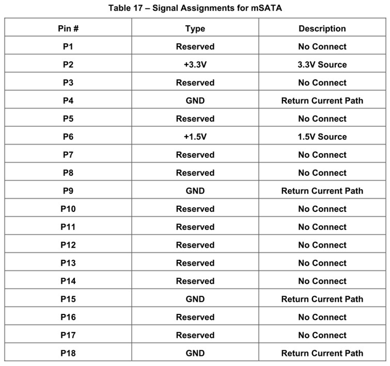

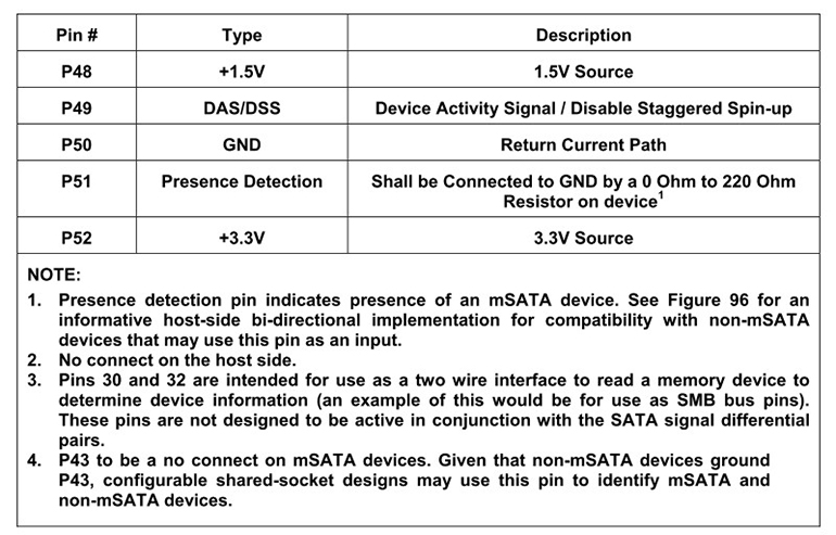
Figure 2: mSATA Pin Definitions
2. SATA Interface of RK3568
The RK3568 chip supports SATA 3.0 and provides the following signals:
SATA0_TXP / SATA0_TXN: Differential transmit signals for SATA channel 0
SATA0_RXP / SATA0_RXN: Differential receive signals for SATA channel 0
3. Schematic Design Steps
3.1 Power Supply Design
The mSATA hard drive requires a 3.3V power supply. Ensure the power supply is stable and provides sufficient current (typically 500mA or more). Add filter capacitors (e.g., 10uF and 0.1uF) during design to reduce noise.
3.2 Differential Signal Connections
Connect the SATA differential signals from the RK3568 to the mSATA interface:
SATA0_TXP → MSATA_TXP
SATA0_TXN → MSATA_TXN
SATA0_RXP → MSATA_RXP
SATA0_RXN → MSATA_RXN
Ensure the differential signal traces are of equal length, with impedance controlled at 100Ω, and minimize vias and bends.
3.3 Ground Connections
Ensure the ground connections of the mSATA interface are well connected to the RK3568's ground. It is recommended to use large ground planes and place decoupling capacitors near the power pins.
3.4 ESD Protection
To enhance electrostatic discharge (ESD) protection, ESD protection devices can be added to the differential signal lines.
4. Reference Schematic
Below is a simplified connection diagram:
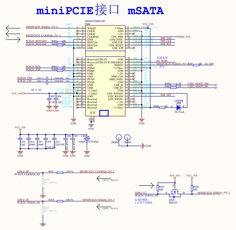
Figure 3: RK3568 and mSATA Hard Drive Connection Diagram
5. PCB Design Considerations
Differential Traces: Maintain equal length for differential signal traces with impedance controlled at 100Ω.
Power Integrity: Ensure the 3.3V power traces are sufficiently wide to reduce voltage drop.
Signal Integrity: Avoid placing high-speed signal lines near noise sources to minimize crosstalk.
6. Debugging and Testing
After completing the design, verify the following steps:
Power Test: Ensure the 3.3V voltage is stable.
Signal Test: Use an oscilloscope to check the quality of the differential signals.
Functional Test: Connect the mSATA hard drive and confirm that the system recognizes it properly.
7. Summary
When designing the connection between the RK3568 and an mSATA hard drive, focus on power supply, differential signals, and ground connections to ensure signal integrity and power stability. Through proper design and testing, stable system operation can be guaranteed.
Hangzhou Weathink Electronics Co., Ltd., as a professional motherboard design company, has extensive experience in using mSATA hard drives. Feel free to contact Weathink at any time. We offer independently designed RK3568 SOM and reliable industrial computers.
https://www.weathink.com/products/hexinban/13.html