
Latest News
-

-

-

-

-

Rockchip RK3568 External SD Card Design
2025-02-13
TI AM6231 Power-On Sequence Requirements
The TI AM6231 is a high-performance embedded processor widely used in industrial control, communication, and consumer electronics. To ensure the stable and reliable startup of the AM6231, a proper power-on sequence design is crucial. This document introduces the power-on sequence requirements for the AM6231, providing guidance for hardware designers to ensure the reliability of the power system.
1. Importance of Power-On Sequence
The power-on sequence refers to the order, delay, and stability requirements for the activation of various power rails during the system startup. A correct power-on sequence ensures that the AM6231 processor and its peripheral circuits are initialized properly, preventing hardware damage or abnormal system startup. The power-on sequence requirements for the AM6231 processor not only involve the order of powering up the power rails but also include the delay and timing control between different power rails.
2. Power-On Sequence Requirements for AM6231
The power-on sequence of the AM6231 involves the following key aspects:
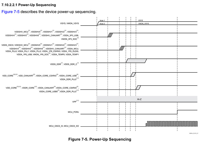
Figure 1: Power-On Sequence Requirements for AM62
2.1 I/O Power (VDDSHVx [x=0-6])
Voltage Output: I/O power is supplied by LDO regulators with a typical voltage of 3.3V or 1.8V, depending on the application requirements.
2.2 Memory Power (VDDS_DDR)
Voltage Output: The memory power is supplied by DCDC converters to provide power to the memory.
2.3 Core Power (VDD_CORE)
Voltage Output: Core power is typically provided by a DCDC converter.
Stability Requirements: The stability of VDD_CORE is critical. Ensure that during power-on, the voltage fluctuation does not exceed 10%, to prevent the processor from failing to start.
Memory Stability: The core power is also critical for the stable operation of the memory.
The key difference between the AM62x series and other processors is the power-up order of these three main power rails. The order is VDDSHVx → VDDS_DDR → VDD_CORE, meaning the I/O power is powered up first, followed by the DDR power, and finally the core voltage. In many other processors, the core power is powered up first, so attention is required in this design.
3. Other Power Rails in the Power-On Sequence
3.1 VSYS
VSYS is the main system power that supplies power to the power management devices, which in turn supply power to all other rails.
3.2 VMON_VSYS
VMON_VSYS is used to monitor the VSYS power through an external resistor divider circuit. For more details, refer to the system power monitoring design guide.
3.3 VDDSHV_CANUART, VDDSHV_MCU, and VDDSHVx [x=0-6]
These are dual-voltage I/O power rails that can operate at 1.8V or 3.3V depending on the application. When using low-power modes for some I/Os, VDDSHV_CANUART should be connected to a always-on power supply. If low-power mode is not used, it should be connected to any valid I/O power rail. When VDDSHV_CANUART is not connected to an always-on power rail and operates at 3.3V, it should rise together with other 3.3V power rails during the 3.3V ramp defined in this waveform.
3.4 VMON_3P3_SOC
This input monitors the 3.3V power rail and should be connected to the corresponding 3.3V power rail.
3.5 Additional Power Rails
For VDDSHV_CANUART, VDDSHV_MCU, and VDDSHVx [x=0-6] operating at 1.8V, they should rise during the 1.8V ramp defined in the waveform, using other 1.8V power supplies.
3.6 VMON_1P8_SOC
This input monitors the 1.8V power rail and should be connected to the corresponding 1.8V power rail.
3.7 VDDS_DDR and VDDS_DDR_C
These should be powered by the same power supply to ensure they ramp up together.
3.8 VDD_CANUART
When using low-power mode for some I/Os, VDD_CANUART should be connected to an always-on power supply; if low-power mode is not used, it should be connected to the same supply as VDD_CORE.
3.9 Voltage Requirements for VDD_CORE and VDDR_CORE
The potential applied to VDDR_CORE should never exceed VDD_CORE + 0.18V. This means that when VDD_CORE is operating at 0.75V, VDD_CORE should rise before VDDR_CORE and fall after VDDR_CORE.
3.10 VPP
VPP is the 1.8V eFuse programming power, which should remain floating (HiZ) or grounded during power-on/off sequences and normal device operation. It should only be used during eFuse programming.
3.11 VDDA_DDR_PLL0
Connected to the VDD_CORE power inside the ALW package.
4. Conclusion
The power-on sequence design for the TI AM6231 is crucial to ensure the system's stability and reliability. Through reasonable power sequencing, delay control, and signal protection, developers can effectively prevent system startup failures or abnormal behavior caused by power issues. It is important to pay close attention to the dependencies between the different power rails and ensure that each power rail starts at the correct time to ensure the proper functioning of the AM6231 processor and its peripherals.
Weathink, as a third-party partner of TI, can provide support in circuit design and recommends using the AM62x SOM designed by Weathink.
WTC-AM62XXS SOM: https://www.weathink.com/products/hexinban/11.html